
Architecture and construction
Convert 2D plans into a 3D model in your own CAD software
Foreign plans arrive as PDF or DWG and someone in your office redraws them by hand. The system does that redrawing: element by element, in your CAD software, with your component catalogue. Everything it cannot read from the source it flags instead of inventing.
Why redrawing foreign plans eats whole weeks of your drafting capacity
Almost no project starts on a blank sheet. A client sends the old floor plans of a building. An engineer sends a DWG with layers named after whoever made them. A previous office sends a PDF printed from a model nobody has any more. Before your team can design anything, someone has to turn that material into a model your office can work in.
That work is not difficult. It is long. Walls get traced, doors get placed, windows get looked up in the dimension chain, rooms get named, storeys get stacked. A mid sized floor takes days, a whole building takes weeks, and it is done by the people who are best at your CAD software, which means the people you would rather have designing. It also does not pay well: the redraw sits inside the fee, invisible to the client. So it gets rushed, and rushed tracing is where the wrong sill height and the missing shaft come from.
- A plan arrives as a flattened PDF with no layers and no blocks at all
- The DWG has geometry on layer 0 and three different layers that all mean interior wall
- Dimension text was exploded years ago, so nothing is associative any more
- Window and door types exist as drawings, not as anything your component catalogue recognises
- Every revision from the other office means checking which lines actually moved
- The person redrawing is your best modeller, not your cheapest one
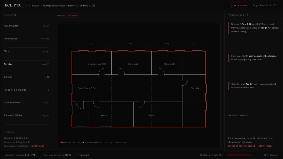
How the system redraws a plan element by element instead of converting it
This is not a file conversion. Conversion produces a pile of lines in a 3D file and calls it a model. The system rebuilds the plan the way a modeller would: it identifies each element, reads its dimensions from the source, matches it against your standards and places it as a real object with real relationships.
- 01
It reads the source material as a set, not as one file
The floor plan, the axis grid, the dimension sheet, the revision history and your own component catalogue go in together. A dimension that is missing on the plan is often present on the schedule, and the system looks there before giving up on it.
- 02
It separates the plan into element classes
Exterior walls, interior walls, doors, windows, columns, stairs and shafts, sanitary objects, rooms and areas. Each class gets its own count of what exists in the source and what has been modelled so far, so progress is visible per class rather than as one percentage.
- 03
It takes dimensions from the drawing, never off the drawing
An opening is measured from its dimension chain, not scaled from pixels. If a chain is missing or contradicts itself, the element does not get a made up size. It gets placed as generic and flagged for a person.
- 04
It matches every element to your catalogue
A window is not drawn as a hole with a frame. It is matched to the type in your own component catalogue, with your glazing, your reveal, your naming. That is what makes the model usable for quantities and tender documents instead of only for pictures.
- 05
It keeps the relationships that make a model a model
Windows and doors are hosted in their walls, so they move with the wall. Rooms are bounded by real geometry, so areas recalculate. The axis grid from the source is preserved as the reference it was.
- 06
It stops where the source is ambiguous
Openings without a dimension, layers that cannot be assigned to one element class, a stair whose direction is not defined in plan. Those come back as a short list of decisions with the source excerpt attached. Nothing on that list is guessed, and nothing on that list silently makes it into the model.
- 07
It hands over the model, not a black box
The result lands in the CAD software your office already uses, in your template, with your layer structure and naming. It is a native model your team edits normally. There is no Eclipta viewer in the middle of your workflow.
Take this with you
A layer convention and an audit prompt for plans you are about to redraw
Most of the pain in a redraw is decided before anyone touches the model, by how the file is organised. Below is a layer and naming convention that machines and humans can both read, plus an audit prompt. Paste your layer list or a plan export into it and you get back the specific things in that file that would block an automated redraw, sorted by how much work they are to fix.
ROLE
You are a CAD standards auditor. You judge whether a 2D drawing is clean
enough that its elements could be rebuilt in 3D without guesswork. You never
invent information that is not in the material I give you.

TARGET CONVENTION (use this as the benchmark)
Layer name: [DISCIPLINE]_[ELEMENT]_[SUBTYPE]_[STATUS]
  DISCIPLINE   AR architecture, ST structure, ME mechanical, EL electrical
  ELEMENT      WALL, DOOR, WIN, COL, STAIR, SHAFT, ROOM, DIM, GRID, TEXT
  SUBTYPE      EXT, INT, LOADBEARING, PARTITION, or your catalogue code
  STATUS       EX existing, NE new, DE demolish
Examples: AR_WALL_EXT_EX / AR_WIN_FE03_NE / AR_DIM_CHAIN / AR_GRID_AXIS

Rules the benchmark assumes:
  1. One element class per layer. No mixed layers.
  2. No geometry on layer 0 and nothing with colour or line type BYBLOCK.
  3. Dimensions are associative objects on their own layer, not exploded text.
  4. Doors and windows are blocks with attributes: type, width, height, sill.
  5. Every exterior opening sits inside a closed dimension chain.
  6. Rooms are closed polylines with a name attribute, not loose label text.
  7. The axis grid exists as its own layer and is named consistently.
  8. Storey height and level reference are stated somewhere in the file set.

INPUT
Below the line I paste one of the following:
  a) my layer list (layer name, colour, line type, entity count), or
  b) a text or DXF export of the plan, or
  c) the block list plus the dimension style list.

TASK
1. Map every layer I gave you to the target convention. State the mapping.
2. List every layer you cannot map to exactly one element class, and say
   what makes it ambiguous.
3. List the blocks that carry no usable attributes.
4. Name the places where a dimension appears to be missing, exploded or
   contradictory, based only on what is visible in my input.
5. Sort every finding into: FIVE MINUTES (rename or move), ONE HOUR
   (re-layer or re-attribute), REAL WORK (redraw or remeasure).
6. Finish with the five actions that remove the most blockers per minute.

RULES
Do not estimate dimensions. Do not assume an element exists because a layer
name suggests it. If my input is not sufficient to judge a point, say which
single piece of information you would need instead of answering anyway.

--- MY MATERIAL BELOW ---
[PASTE YOUR LAYER LIST OR PLAN EXPORT HERE]
- Export the layer list from your CAD software as text or CSV, including entity counts.
- Paste the whole prompt into any capable chat assistant, then paste your export under the last line.
- Work the FIVE MINUTES findings immediately. They usually remove half the ambiguity in a file.
- Adopt the convention in your own template so the next project starts clean instead of getting cleaned.
- Run it once on a plan you received from another office to see how much of the redraw effort is caused by their file rather than by the building.
This convention and prompt clean up your own stock and tell you how bad an incoming file is. They do not draw anything. The prompt sees the description of your geometry, never the geometry, so it cannot measure an opening, place a single wall or produce a 3D model. Turning the plan itself into a model is still a person with your CAD software open, which is exactly the part the built system takes over.
Where the audit stops and the built system starts
The gift above works on the description of a file. The built system works inside the file. It opens the plan, reads the dimension chains, matches types against your catalogue and places elements one after another until the floor is modelled. It is built for one office at a time, because a component catalogue and a template are never generic.
The honest part matters more here than in most use cases. A model that quietly invents four window openings is worse than no model, because the invention stays invisible until someone builds it. So the rule is fixed: anything unambiguous gets modelled automatically, anything ambiguous stops and waits for a person with the source excerpt in front of them, and anything that becomes a commitment to a client goes to a person by default. The system reports what it did not know instead of filling gaps to look complete.
- Runs inside the CAD software your office already uses, in your template
- Uses your component catalogue, so types carry your naming and your specifications
- Dimensions come from the drawing's dimension chains, never scaled off geometry
- Hosted relationships are preserved, so the model behaves like a model
- Elements it cannot resolve are placed as generic and flagged, with the source shown
- Progress is visible per element class while it runs, not just at the end
- The output is a native file you own. Nothing depends on us afterwards
Frequently asked questions
Can I convert a 2D floor plan into a 3D model automatically?
Parts of it, reliably. Walls, openings, columns, rooms and levels can be rebuilt automatically when the source states their dimensions. What cannot be done automatically is inventing information the plan does not contain, such as an opening with no dimension chain or a wall build up that was never specified. In a working setup those elements are placed as generic and flagged, and a person resolves the short list.
What is the difference between file conversion and redrawing a plan?
A conversion moves geometry from one format into another. You end up with lines and surfaces that look right and carry no information: a wall that is not a wall, a window that is not a component. Redrawing means each element is identified and placed as a real object of the right type, hosted correctly, matched to your catalogue. Only the second one is useful for quantities, tenders and later design changes.
Which CAD software does this work with?
The one your office already uses. The system is built to write into your environment and your template rather than to export from ours. Which software you are on is one of the first questions in the call, because it decides how the system is built. If your workflow ends in an open exchange format, that is the delivery target instead.
Can I not just do this with ChatGPT?
You can use a chat assistant for exactly what the prompt on this page does: reason about a list, a convention or a description. It cannot open your CAD file, read a dimension chain, place an element or keep a hosted relationship. The moment the work involves acting inside your software on your real project files, repeatedly and without someone pasting things back and forth, it needs a built system rather than a chat window.
Does our project data leave the office?
That is decided before anything is built, and it is decided by you. Setups range from fully on premise, where plans never leave your network, to a hosted setup with a defined provider and a defined retention. Client plans and site data are usually the most sensitive material an architecture office holds, so the data path is part of the design, not a setting somebody flips afterwards.
What does a system like this cost and how long does it take to build?
It is a build, not a subscription per seat, and the price depends on how many element classes you need and how ordered your standards are. The rough shape: a first working version on one real project type, then extension. An office with a clean template and a real component catalogue gets there faster, which is one reason the free convention on this page is worth an afternoon.
What happens when the source plan is bad, and who checks the result?
A flattened PDF without dimensions holds less information than a model needs, and nothing changes that. The system separates what is genuinely readable from what is not, models the first part completely and hands you the second part as a defined list of questions with the source excerpt attached. Your team checks and signs off, because the professional responsibility sits with them and never with the system.
Apply for a build
If your office spends weeks a year redrawing other people's plans, that is a clear scope with a clear boundary. Tell us which CAD software you work in, what your incoming material looks like and how your component catalogue is organised. We take on a small number of builds, so the call is a fit check in both directions.
Apply